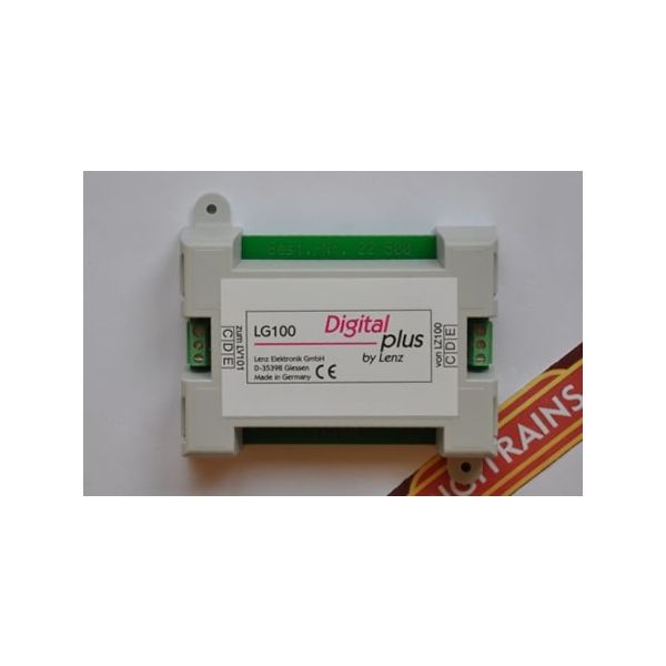
.The brake module LG100 serves to provide prototypical slowing and stopping of digital locomotives in front of a 'red' signal.
LG100 generates the control signals for a booster, just like the command station LZ100. The LG100 does not have an amplified output for connection to the track. For operation, a booster LV100 with its corresponding transformer is needed
The brake module sends a digital signal that all locomotive decoders can react to.This is possible through the transmission of a special digital address.
. This address is received, evaluated and acted on by all locomotive decoders that are in an area fed by the brake module.
. The brake module sends the command "speed step 0" as speed data. This order stops the locomotive, after it slows down at the preset deceleration rate.
. You must use suitable devices to ensure that the locomotive decoder receives the digital signal from the brake module at the right time.
. Divide the track in front of the signal into two areas .
The first part, the operating section, must be at least as long as the longest train on the layout.
. The length of the second part, the stop section, is determined by the deceleration rate set in the locomotive decoder. This area must be long enough to safely bring the locomotive to a complete stop.
. The operating and brake sections are in the following referred to as a 'block'. At beginning and end of the block you need to cut both rails. Then install a polarity free (isolated) track contact at the beginning of the stop area .
Relay 1 (twin-coil) serves to switch the block between command station signal 'A' and the brake module signal 'B'.
Relay 2 (twin-coil) ensures that when the signal shows 'green', the section is not switched to the brake module signal (This relay activates the track contact, TC). If the signal shows 'green', then the connection to the track contact is interrupted by relay 2. In other words, relay 2 is connected in parallel with the signal drive and switched with it.
The sequence of events at a 'red' signal
. When a train enters the block, the normal digital signal (from command station LZ100 and its booster LV100) is present in the block.
. When the locomotive reaches the stop section, the track contact (TC) is activated and relay 1 switches the block (both operating and stop sections) from track signal 'A' from the command station to track signal 'B' from the brake module.
. Because the whole block is switched over to the signal from the brake module, this setup works for pushed trains as well (push-pull trains with cab cars). In this case, the track contact (TC) is activated by the first car of the train.
. The train must be fully inside the block at this point.
. The locomotive decoder receives the signal from the brake module, decodes the command to stop, and decelerates the locomotive at the pre-programmed deceleration rate to a complete stop.
. If the signal now is set to 'green', then relay 1 switches the block back to the command station signal. The locomotive decoder again receives its 'old' speed step and the locomotive starts up with the pre-programmed acceleration rate.
. At the same time relay 2 breaks the connection between the track contact (TC) and relay 1, so that any further pulses will not lead to a new braking sequence.
. When the train leaves the block, the signal is set to 'red' again, and relay 2 reestablishes the connection between track contact (TC) and relay 1. Then the next train will come to a stop in front of the signal.
. If you want to be able to operate a train in this block in the opposite direction with a signal showing red, you need to use another relay to deactivate the track contact.
Important:
If the block is fed the signal from the brake module, then the double gaps in the track between the block and the section before and after must not be run over. If they are, you will have a short circuit and DIGITAL plus will switch into EMERGENCY STOP!
As a polarity free (isolated) track contact, you can use, for example, the ROCO contact track 42518, or also a REED contact. In case of the latter, you must install a magnet in the cab car of pushed trains (in the first car in the direction of travel).
Another option is to use a current sensor. Then you must have a double gap in the track between the operating and the stop sections, and monitor the stop section with the current sensor. Now you switch over to the brake module as soon as a current user enters the stop section. In pushed trains you need to equip the first car with interior lighting. If you use the Arnold universal relay 86077 as the relay, the track contact does not have to be isolated. Please see the manual of the universal relay for information on how to connect such track contacts (for example Arnold 7440).
The idea of Digitrains was conceived over the dinner table and grew very slowly as doubts calmed missionary zeal. We finally took the plunge in January 2005 and are fortunate to be dealers for some of the best and most user friendly DCC equipment available.
 MENU
MENU