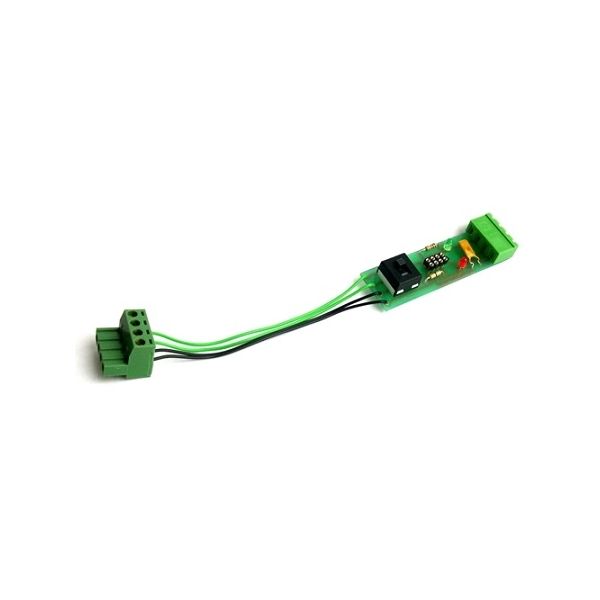
This device takes power from your DCC controller to a circuit board that has an 8 pin decoder connector and output connections for the motor feed. It includes test LEDs.
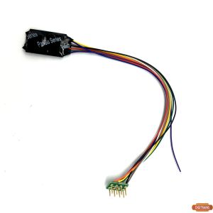
Your new DCC71 is specially designed to be used with our Prodigy Advance systems but can be adapted onto other systems by
removing the DCC60 plug.
WE SUGGEST THAT THE CONTROL UNIT IS SWITCHED OFF WHEN INSERTING OR REMOVING THE DCC71
ALWAYS PLACE THE DCC71 ON A SOFT NON CONDUCTIVE SURFACE
Insert the DCC71 plug into the matching socket at the rear of your Prodigy base unit, insert the decoder that you wish to test into the
NEM medium socket provided (PLEASE NOTE THE NUMBER 1 PIN HAS BEEN MARKED ON THE UNDER SIDE OF THE
PCB). Your DCC controller can now be used to perform all the tasks as normal with the plate acting as a static loco. The small switch
can be moved from left to right for switching the decoder from main to programming track as necessary, Prodigy users will regard
LEFT or GREEN wires as the programming track and the RIGHT or BLACK wires as the main. All other users will need to note their
connections.
For new decoders always set to programming and, if supported, it is a good idea to read the address and then reprogram and confirm the
change with the READ facility again. Many decoders require a feed through the motor to program correctly and if no main track and
loco is to be connected then please connect the bulb provided into the equivalent right hand track output terminals.
Assuming the decoder has worked successfully you can then switch to the main track and test it’s operation but closely inspect and
proceed cautiously with any decoder that does not work as expected as it might be faulty, switching to main track can in many cases
cause such decoders to overheat and fail.
ALL DCC LOCO’S/EQUIPMENT MUST BE DISCONNECTED FROM THE TRACK BEFORE CONNECTING THE DECODER
OUTPUT!
The main track setting can be used to power the bulb and test the directional lighting or if desired your layout can be connected and an
analogue loco run via the DC motor output from the decoder. Acceleration, deceleration and voltage settings will have an effect on the
loco’s running characteristics and will give a good indication as to how the decoder will perform when installed.
An 1100ma 30v thermal switch (MCB) has been placed inline with this output and is designed to offer some protection in the event of
an overload but this will depend on the rating of the decoder.
CAUTION When in use the MCB will be warm and in the event of an overload it will become extremely hot!
You now have the ability to run in a new loco and test the decoder without the need to dismantle or rewire any of the components and
avoid failed installations. After you have installed the decoder in your loco always read and reprogram as before in the event of faulty
wires or defective connections.
GUARANTEE: We undertake to replace, free of charge, any parts found defective within the lifetime of the unit, providing the item
has not been tampered with and parts are still available for such a repair. This guarantee covers only the supply of replacement parts,
labour cost for fitting of same and the cost of returning the unit to the customer or retailer. This Guarantee does not affect your
Statutory Rights. We reserve the right to vary design or specification without notice.
The idea of Digitrains was conceived over the dinner table and grew very slowly as doubts calmed missionary zeal. We finally took the plunge in January 2005 and are fortunate to be dealers for some of the best and most user friendly DCC equipment available.
 MENU
MENU